The Freebody tool in Femap enables the viewing of internal loads in a finite element model. This is convenient when trying to capture the load as it passes through a part or assembly. Freebodies will show either forces and/ or moments. For solids, you can only view forces in the Tx/Ty/Tz directions. Solids do not pass rotational degrees of freedom (DOF) and thus do not pass moments. Plates and other element types that carry rotational DOF will show both forces and moments. In both instances, these loads are nodal.
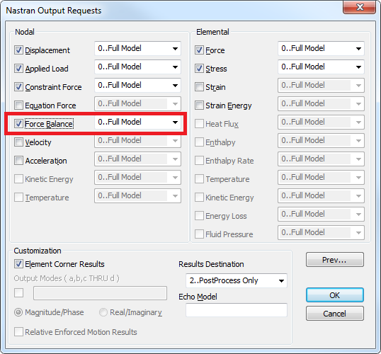
Freebodies cannot be made without requested the necessary data from the solver run. Nastran calls this Grid Point Force Balance (GPFB). Recovery of GPFB data is not enabled by default. To request it, you must enable Force Balance in the Femap Nastran Output Requests dialog.
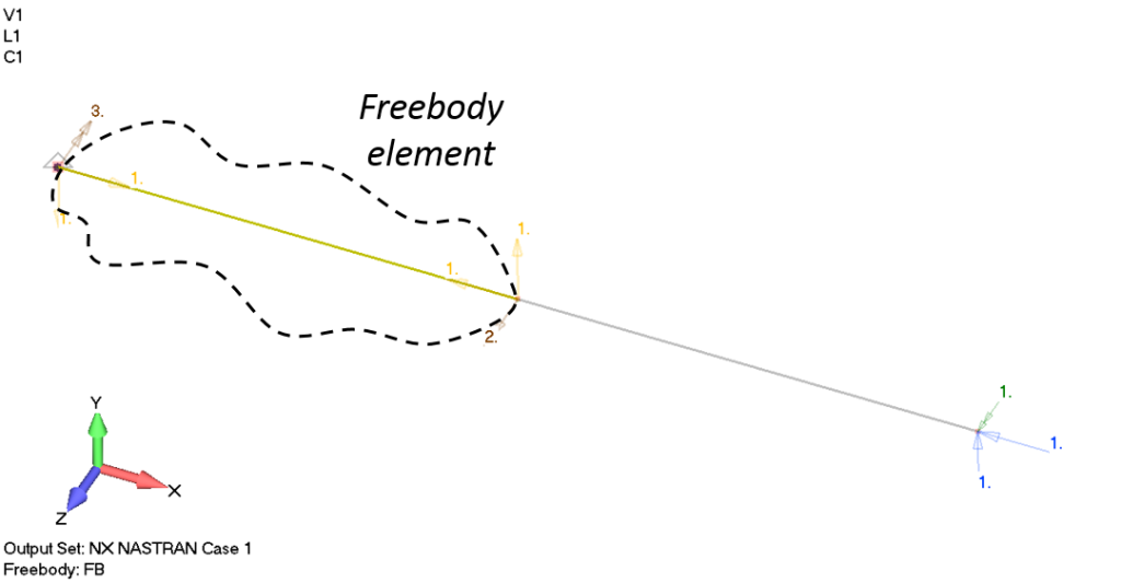
Many people struggle to implement freebodies due to the inherent complexity of the tool. This post will feature an extremely simple example to help. The model below has two rigid elements. Rigid elements were chosen for this example since we are focused on loading and not the stiffness or stress in the model.
A fixed constraint is placed on the left node of the left rigid element. An applied external load is shown at the right. Each of these loads has their associated arrow vectors displayed. A simple Freebody will be demonstrated first, so the left rigid element is selected (steps not shown). Freebody forces are indicated as if the elements are contained in their own system (internal loads should be in equilibrium), so there is a balanced set of forces and moments for the freebody element.
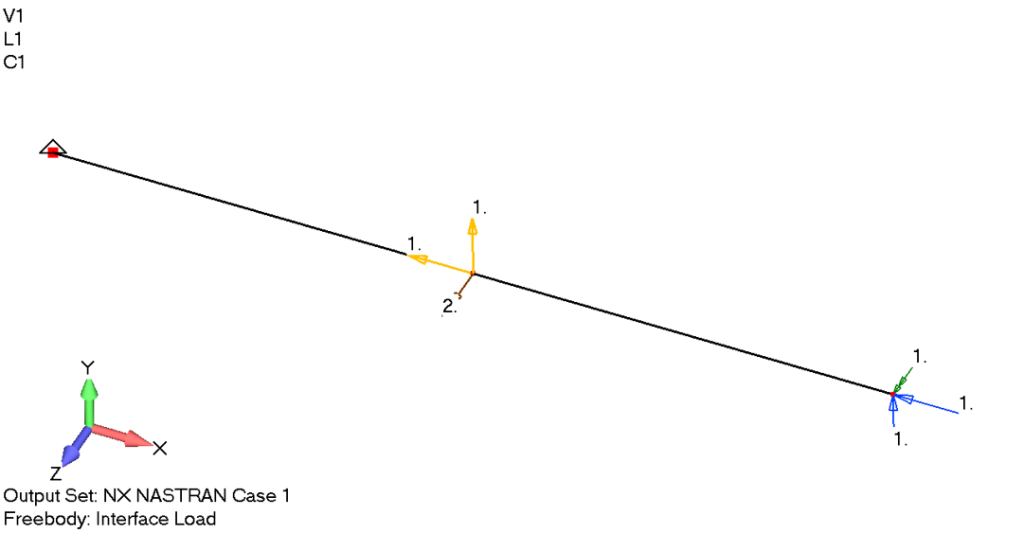
Now let’s look at an Interface Load. This type of Femap freebody can show non-equilibrium set of internal loads by specifying interface nodes. The center node is selected:
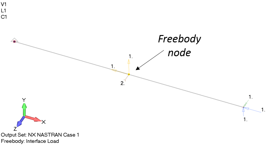
The left element is still selected as the sole freebody element.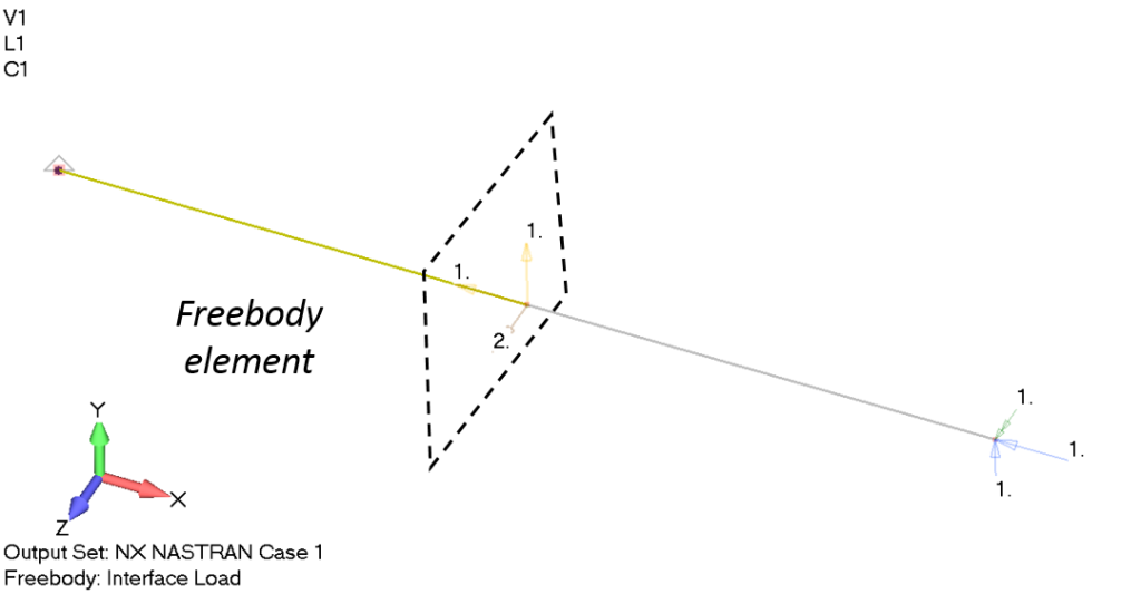
Below, the left element is showing the load transfered from the right element. Directionally speaking, this is the load on the left element from the right side element.
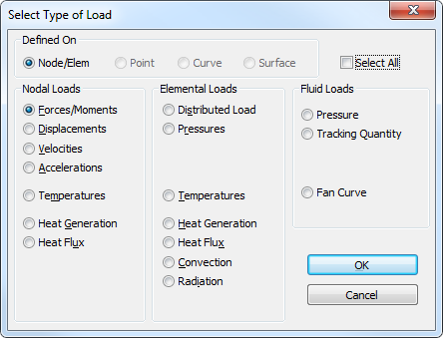
Finally, what if we wanted to see the reaction load on the left element from the constraint. We could either revert back to the simple Freebody display mode, add in an interface element on the left side, or we can generate the reaction as a new load as display it as a normal external load vector. To do this, we’ll have to navigate to Model > Load from Output:
Then we’ll have to select the source of the loading with Create Loads From Output dialog:
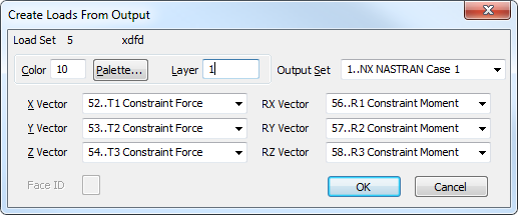
Following this dialog, a new load definition will be created in the model. Removing all freebodies from view, we have this:
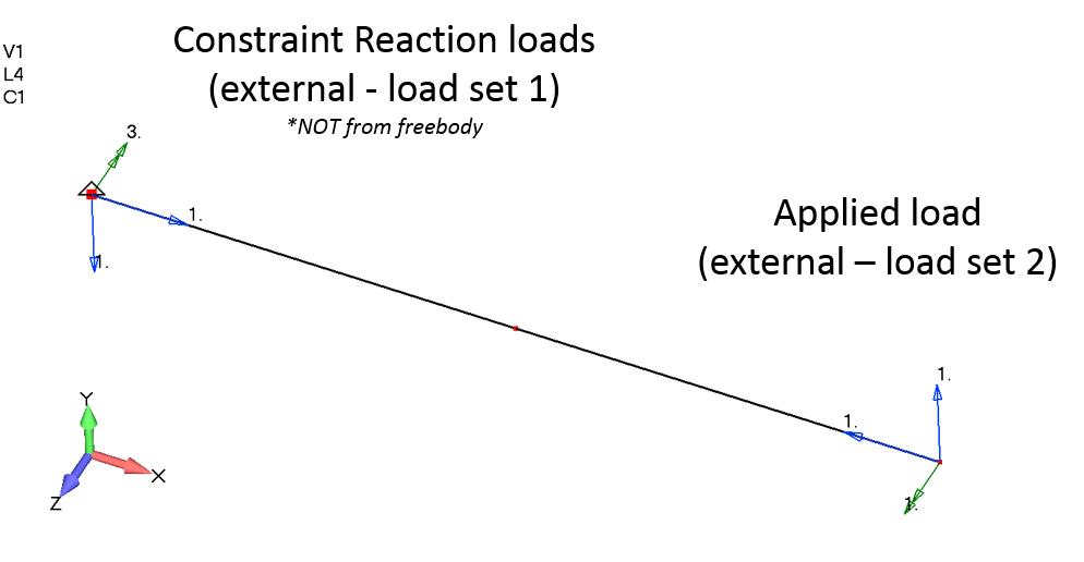
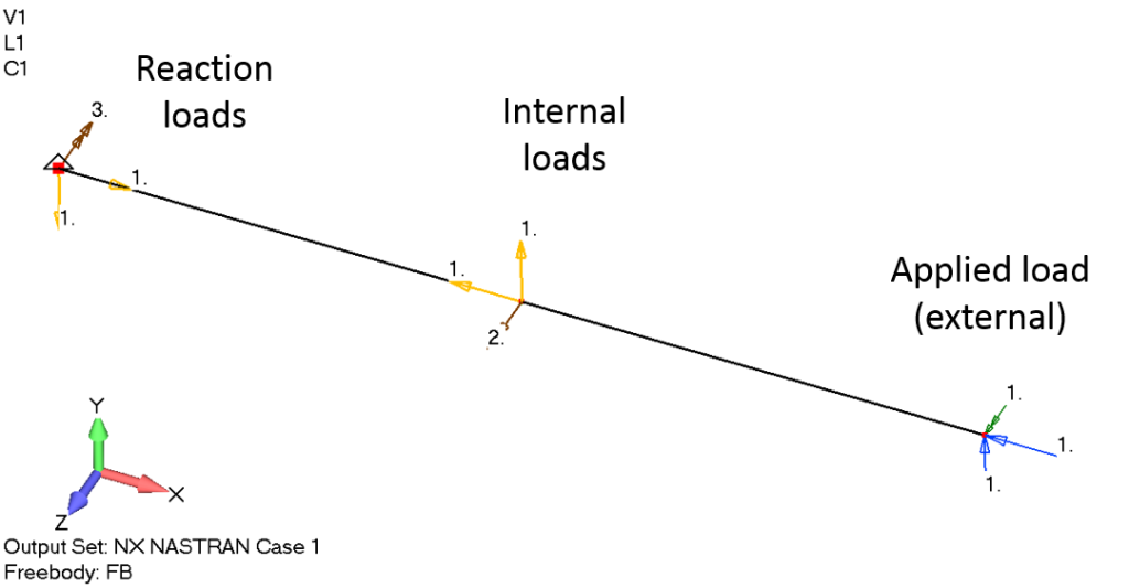
Lastly, we can see the reaction, internal, and externally applied load all at once. This leads into a warning. Beware of how you interpret the visibility of force and moment vectors in Femap when viewing Freebody plots. You may end up with something that is not an effective free body diagram (in the sense of the engineering term). You must be cognizant of the consistency when choosing what combination of boundary conditions and freebody vectors to show.
Disclaimer: The first edition of Learning Femap does not cover Freebodies, as they are what I consider an “advanced” feature of Femap. However, a discussion is indeed planned for a later release.
For more information, please see the www.structures.aero (SDA) webpage with the Understanding Freebodies webinar:
https://structures.aero/portfolio-item/understanding-freebodies-with-femap/