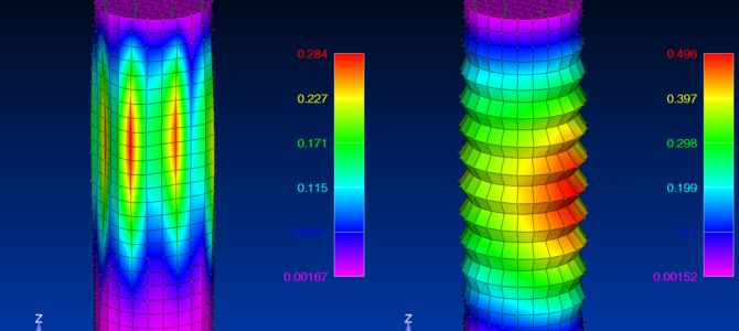
TLDR: Compressive loads/stresses within any long, thin structure can cause structural instabilities known as buckling. Buckling occurs when deflections continue to increase even if load is not. This stability analysis is a key component of structural analysis. This article attempts to provide insight for the appropriate buckling factor of safety associated with linear finite element analysis outputs, specifically, the Eigenvalues (aka “load factor” or “buckling load factor”) produced by SOL105 in Nastran. These Eigenvalues are the factor of the applied load that will lead to buckling, and are therefore used in establishing Margin of Safety against buckling/stability. Buckling is a tad more complicated than a simple static solution, and so the analyst may wish to consider additional factors related to the behind the scenes math occurring in Nastran solution process.
A factor of safety for strength typically used in aerospace is 1.5 against limit loads. A factor of safety on linear Eigenvalue buckling greater than 1.5 against limit loads may be warranted to account for uncertainties with such an analysis. With rapidly changing stiffness near the buckling threshold, determining where exact you sit on this precipice using Eigenvalue analysis can be subject to a few uncertainties, briefly detailed below.
With linear SOL105 buckling, small deflections are assumed. The differential stiffness matrix [Kd] is calculated about the initial loading point, and it would take an iterative procedure to find the more appropriate matrix about the true buckling inflection point. In that case, Nastran can indeed compute nonlinear buckling through a more advanced SOL105/106 analysis or any nonlinear static solution (pure SOL106, 400, or 600 series solution types), but those are seldom carried out during early design iterations. They are also not recommended, because they take more setup analysis time, and require more parameters which potentially introduce more uncertainty, and so it is better to solve the design issue through linear buckling analysis instead. An analyst may wish to run nonlinear buckling analysis when comparing test results, or if the structure is already built and the margin must be absolutely proven to support program needs.
No material changes are considered, such as yielding (plasticity reduction factor). Think about it! Did you enter a stress strain slope to solve that SOL105 run? Of course not, but it should make you realize that the solver knows nothing about the softening of the structure as the yield point is reached (reduced in stress strain curve slope).
“Initial imperfections” are not typically modeled. Although not an issue associated directly with linear buckling, it is associated here due to industry practice use of linear buckling to establish Margin of Safety. These are real, physical kinks (as opposed to discretization error-related “kinks”) that can make a structure more susceptible to instabilities. More on that discussion can be found in references related to honeycomb core panels and the associated coefficients on facesheet stability (wrinkling) closed form solutions.
Linear buckling doesn’t account for follower forces. Boundary conditions are another source of uncertainty, and they are a major contributor to stability. We often make assumptions about the level of support afforded to the breakout models. Nor do we necessarily represent the details of how the manufactured structure comes together such as with panel edges in a global model run. Do we really have the rotational stiffness of a skin panel edge modeled perfectly? Usually not. Copious use of rigids and interpolation elements, and occasional use of element offsets, also add uncertainty to model stiffness.
Mesh discretization is another factor. Does each buckling mode shape have five grid points per half sine wave as recommended by the reference manual? Not always. Has this been ensured for each mode? Larger models might contain many buckling modes, which make it difficult to check this assumption in practice.
The previous factors show that linear Eigenvalue buckling analysis may not be conservative. The point was certainly not to make the case for nonlinear buckling analysis in design. Linear buckling analysis remains a tremendous tool for the structural analyst. To account for inadequacies, it is typical in industrial practice to carry a supplemental factor on the recovered buckling Eigenvalue when writing a buckling Margin of Safety. It’s not uncommon to see a required buckling Eigenvalue of 2.0 against limit loads. As a reminder, this factor is for stability margins calculated with of FEA, and not hand calculation methods.
One last note: it may be useful towards later program stages (past the normal design stage) to run a nonlinear buckling analysis as a check on assumptions and risk mitigation procedure. The author recommends this from prior experience!
What are your thoughts? What is customary at your company, and why?
References:
- Shigley’s Mechanical Engineering Design
- NX Nastran User Manual

great article eric. I do run a lot of SOL105 at work and definitely would like to have more assurances on what is actual “reality”. I am seeing a lot of our structures near an EV = 1.00 @ ULT! Definitely makes me a bit worried. On the flip side, SOL105 doesn’t take into account any type of post-buckled capabilities, so it does make me less concerned, as you are aware, most of aircraft structures are redundant systems, something SOL105 wouldnt take into account and something that could be captured with a SOL106 run.
Good point on the redundancies, Scott. Then one would have to introduce this consideration into their analysis, i.e. are they looking at one of many stringers, or are they looking at the global collapse of a monocoque component.